 OpenWiring
#18. Import and export
PDF in the toolbar (or File ▸ Export ▸ PDF…) creates a vector PDF in A3.
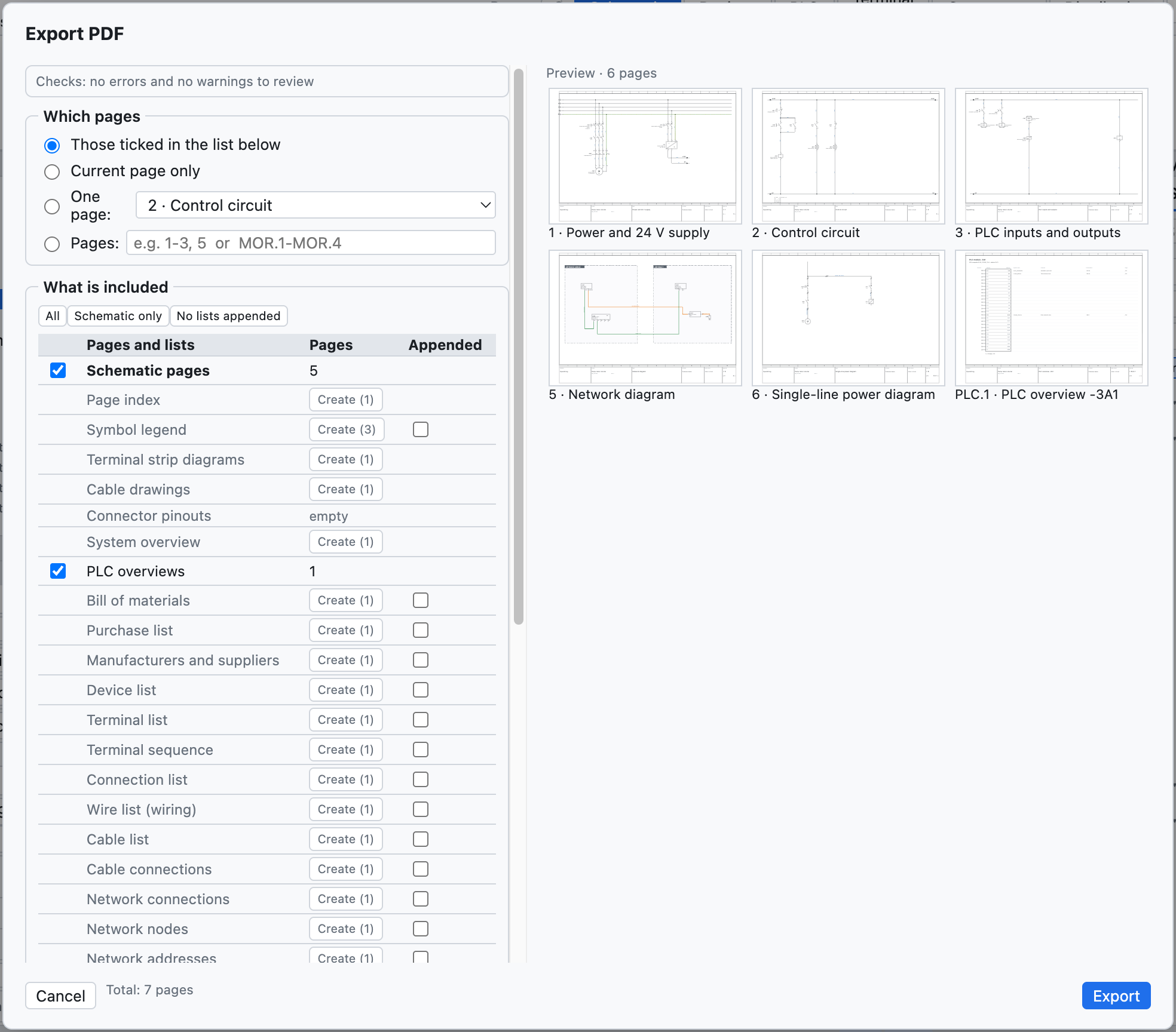
The PDF options.
| Option | Effect |
|---|---|
| Those ticked in the list below, Current page only, One page, Pages | which pages; the range is written with the project numbers (1-3, 5 or 200-205) |
| Initial index page | clickable index of pages and lists |
| Lists at the end | bill of materials, devices, terminals, connections, PLC I/O after the schematics |
| Black and white for printing | wires and wire numbers in black |
| Compact file (smaller) | on by default: a file about ten times smaller, same drawing, references and bookmarks still clickable |
| Add the pages of other cabinets with devices of the chosen cabinets | appears when some cabinets are left out: adds the pages of other cabinets where devices of the printed cabinets are drawn (chapter 11) |
| PDF language, Second language | the PDF in another language, without changing the project |
In the PDF the references are clickable (contacts ↔ coil, interruption points between pages, PLC, overviews), as are the positions in the lists and the index; the PDF has bookmarks for pages and lists.
#Printing
File ▸ Print… (⌘P) sends the pages to the printer in A3 landscape, one page per sheet.
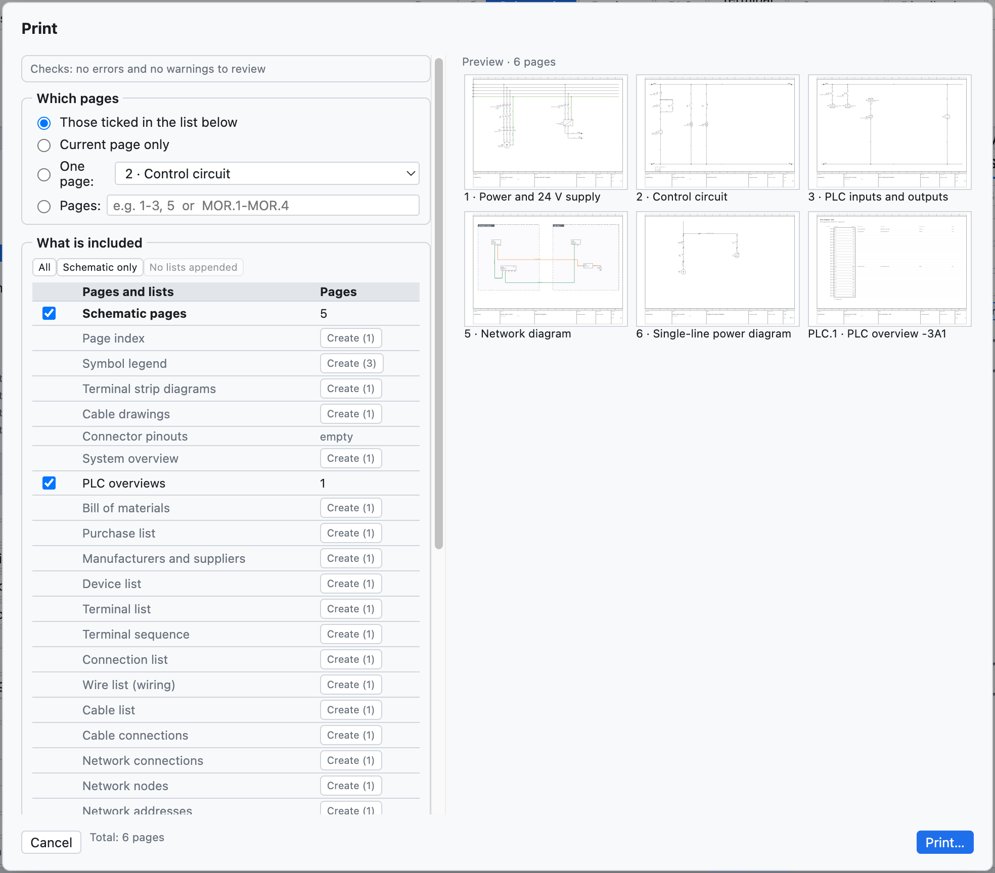
The print options: pages, black and white, language.
To print the lists too, first create the list pages (chapter 14).
#DXF
| Command | Result |
|---|---|
| File ▸ Export ▸ DXF of the current page | a DXF R12 at 1:1 scale, in mm |
| File ▸ Export ▸ DXF of the whole project (ZIP) | one DXF per page, collected in a ZIP archive |
| on the layout page | the drilling DXF of the plate (chapter 12) |
The DXF files have the layers CORNICE, CARTIGLIO, SIMBOLI, FILI, TESTI, SIGLE, NUMERI_FILO (plus CAVI and QUADRI where needed) and open in AutoCAD, DraftSight, LibreCAD and other CAD programs. The DWG format is not available: open the DXF and save it as DWG from the CAD.
#Excel and CSV
- Every list is exported as CSV (separator
;) from the Lists view. - The device navigator exports and re-imports Excel (chapter 7).
- The PLC view exports for TIA Portal, CODESYS, PLCopen and the I/O list (chapter 10).
- The labels come out in Excel or CSV (chapter 14).
- The translation dictionary comes out in CSV (chapter 16).
#Importing schematics from PDF (SEE Electrical and others)
File ▸ Import ▸ Schematic from PDF (SEE Electrical…)… creates a new project from a schematic exported as a vector PDF from another CAD. It was tested with a real SEE Electrical project of 207 pages, imported in a few seconds.
What is rebuilt:
- sheets: one for each schematic sheet, with number and title from the title block; the title prefix
(
Q1.1 Ingresso linea) becomes the location+Q1.1; cover and lists of the source CAD are skipped; - real wires, with the colour of the drawing (blue → BU, green-yellow → PE, red → RD…) and the name
written next to them (
L1-1.1,200.01) as wire number; - components with the nearest tag, the terminals where the wires arrive and their names
(
1/L1,A1,95); - terminal strip terminals, multi-level too (
X1.1.12:1A); - interruption points between pages, paired by name or from the
sheet.columnreferences; - free texts and component texts.
To be rechecked: components are recognised from the graphics and do not know whether they are coils or contacts (so no contact image); some elements remain graphics without a tag. Project ▸ Check reports interrupted conductors and interruption points without a counterpart. A scanned PDF (an image) cannot be imported.
#Other imports
| Command | What it imports | See |
|---|---|---|
| Parts EDZ / XML / CSV… | manufacturer parts, with pictures, terminals, drawing and commercial data (CSV) | chapter 7 |
| QElectroTech symbols… | .elmt, .qet components, archives |
chapter 13 |
| Macros… | .ecmacro files |
chapter 13 |
| Compare with an .ecad file… | differences with another project | chapter 15 |
| Import DXF… in the title block editor | title block drawn in another CAD | chapter 13 |
| Import variables (PLC view) | tag table from TIA Portal, CODESYS, CSV | chapter 10 |
| Pages as text | pages written by an AI assistant or a script | chapter 17 |
#Other exports
| Command | Result |
|---|---|
| PLCopen XML (PLC variables) | global variables for CODESYS and compatible environments |
| Parts as XML (EPLAN format) | library parts in an XML file in the EPLAN format |
| Translation dictionary (CSV) | table Italiano;English;Deutsch |
Edit this page on GitHub · OpenWiring 2.0.6 · GPL-3.0