 OpenWiring
#12. Cabinet layout
The layout page is the mounting view of the cabinet plate: DIN rails, cable ducts and devices to scale, with dimensions. It is used to check that everything fits, for drilling and to estimate the length of the wires.
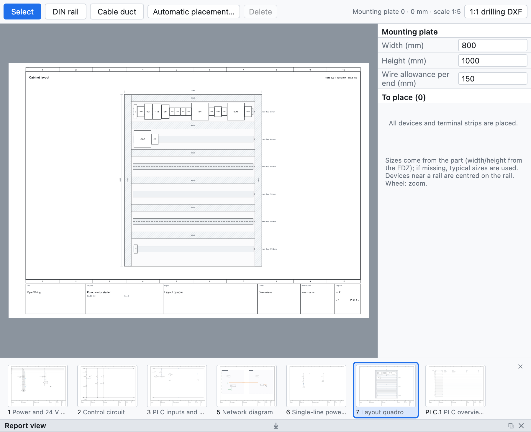
A layout created with automatic placement: two rows of rails with cable ducts and the devices of the example project.
#Creating the layout
- + Layout under the tree creates a layout page with the plate at a standard scale (1:5, 1:10…), dimensioned.
- In the panel on the right set width and height of the plate in mm and the wire spare per end.
- Assign the page to a location to see only the devices of that cabinet.
#DIN rails and cable ducts
With DIN rail and Cable duct in the view bar, drag on the plate to draw them. Each rail shows the free millimetres.
#Placing the devices
- The To place list shows the devices and terminal strips not yet placed: drag them onto the plate.
- Devices near a rail are centred on the rail.
- The dimensions come from the part (width and height of the EDZ), otherwise they are typical values; a terminal strip is as wide as its terminals (a multi-level terminal takes one pitch).
- Automatic placement creates rows of cable ducts and rails if missing and places on the rails all the devices not yet placed.
#Checks
The check reports devices outside the plate, overlapping devices and full rails.
#Drilling
1:1 drilling DXF exports plate, rails, cable ducts, device outlines and Ø 5.5 fixing holes at real scale, ready for machining.
#Bill of materials and wire lengths
- Rails and cable ducts with a part go into the bill of materials in metres.
- The wire list (wiring) gives for each wire cross-section, colour, ferrules (DIN 46228) and the length estimated from the layout: route between the devices plus the spare at the ends.
- The purchase list sums the loose wire by cross-section and colour with 10% extra (chapter 14).
Edit this page on GitHub · OpenWiring 2.0.6 · GPL-3.0