 OpenWiring
#5. Drawing the schematic
#Inserting symbols
- In the library on the right (Symbols tab) click a symbol. The Search… field filters by name («contact», «motor»…).
- Click on the page: the symbol is inserted snapped to the grid and stays active, so you can insert more of the same.
- R rotates the symbol by 90° before inserting it.
- Esc or a right click ends the insertion.
Each new symbol gets a free tag according to the project template (for example -2K3, see
chapter 6). For an auxiliary contact just inserted, a list of the devices to pair it with opens: coils and apparatus
of the project, first those with the same letter, each with description, position and number of contacts.
The list is filtered as you type; you can also type a new tag. The program offers the last one chosen again.
#The included symbols
| Category | Symbols |
|---|---|
| Coils and contacts | relay/contactor coil, timed coil, NO contact, NC contact, changeover contact, 3-pole power contacts |
| Commands | NO pushbutton, NC pushbutton, mushroom emergency stop, selector switch, limit switch, 3-wire PNP proximity sensor |
| Protection | fuse, 1P, 2P and 3P miniature circuit breakers, 3P motor protection switch, 3P thermal overload relay |
| Loads | three-phase and single-phase motor, indicator lamp, solenoid valve, 230 V AC / 24 V DC power supply, transformer |
| Terminals and connections | terminal, PE terminal, disconnect terminal, fuse terminal, socket pin, plug pin and socket+plug pair, potential point, protective earth PE, outgoing and incoming interruption points |
| PLC | digital input and output, analog input and output, L+/M card supply |
| Networks and buses | 2-port node (IN/OUT or P1/P2), 1-port node, 5-port switch, termination |
| Single-line | circuit breaker, motor protection switch, disconnector, fuse, contactor, motor, transformer, inverter, power supply, load |
Other symbols can be drawn with the editor or imported from QElectroTech and from the manufacturers' EDZ files (chapter 13 and chapter 7).
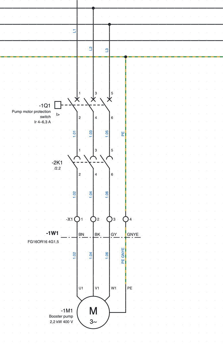
The motor feeder on page 1: motor protection switch -1Q1, power contacts of contactor -2K1, terminal
strip -X1, cable -1W1 and motor -1M1.
#Drawing wires
- Press W or Wire.
- Click the start point: a connection point, an existing wire or a free point.
- Click for each corner. Each segment is always horizontal or vertical; before the click the preview shows the L-shaped path.
- The wire ends by itself when you click a connection point or another wire. Otherwise finish it with a double click, Enter or a right click.
- Esc cancels the wire being drawn.
Free connection points are highlighted in green while drawing. When arriving at a wire slightly off to the side, the segment continues straight up to the wire.
#Junctions and crossings
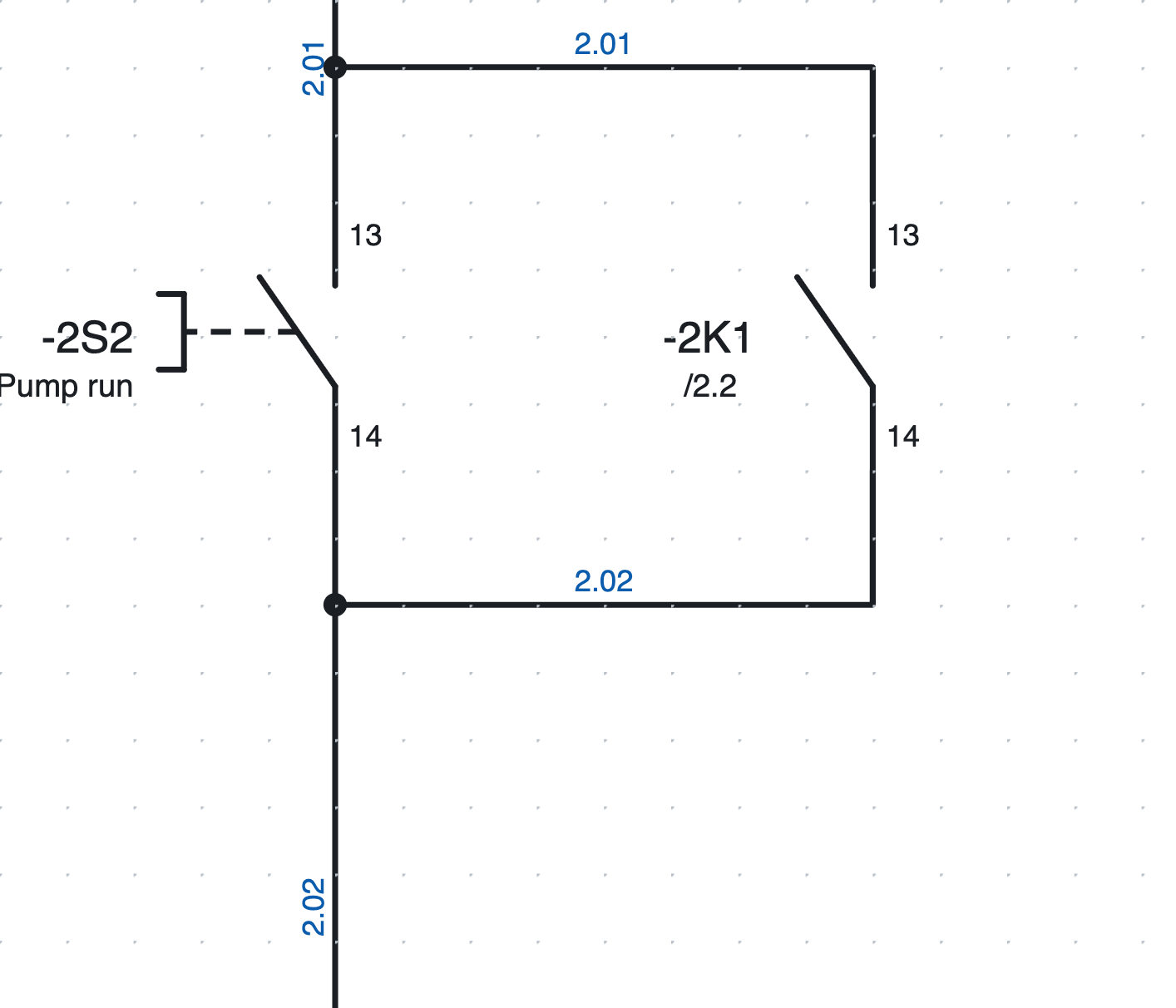
The self-holding junctions on page 2: the dot shows the connection.
- A wire that ends on another wire forms a T-junction, drawn with a dot.
- Two wires that cross without a dot are not connected.
- The dot is not drawn by hand: the program places it where the wires are really connected.
#Editing wires
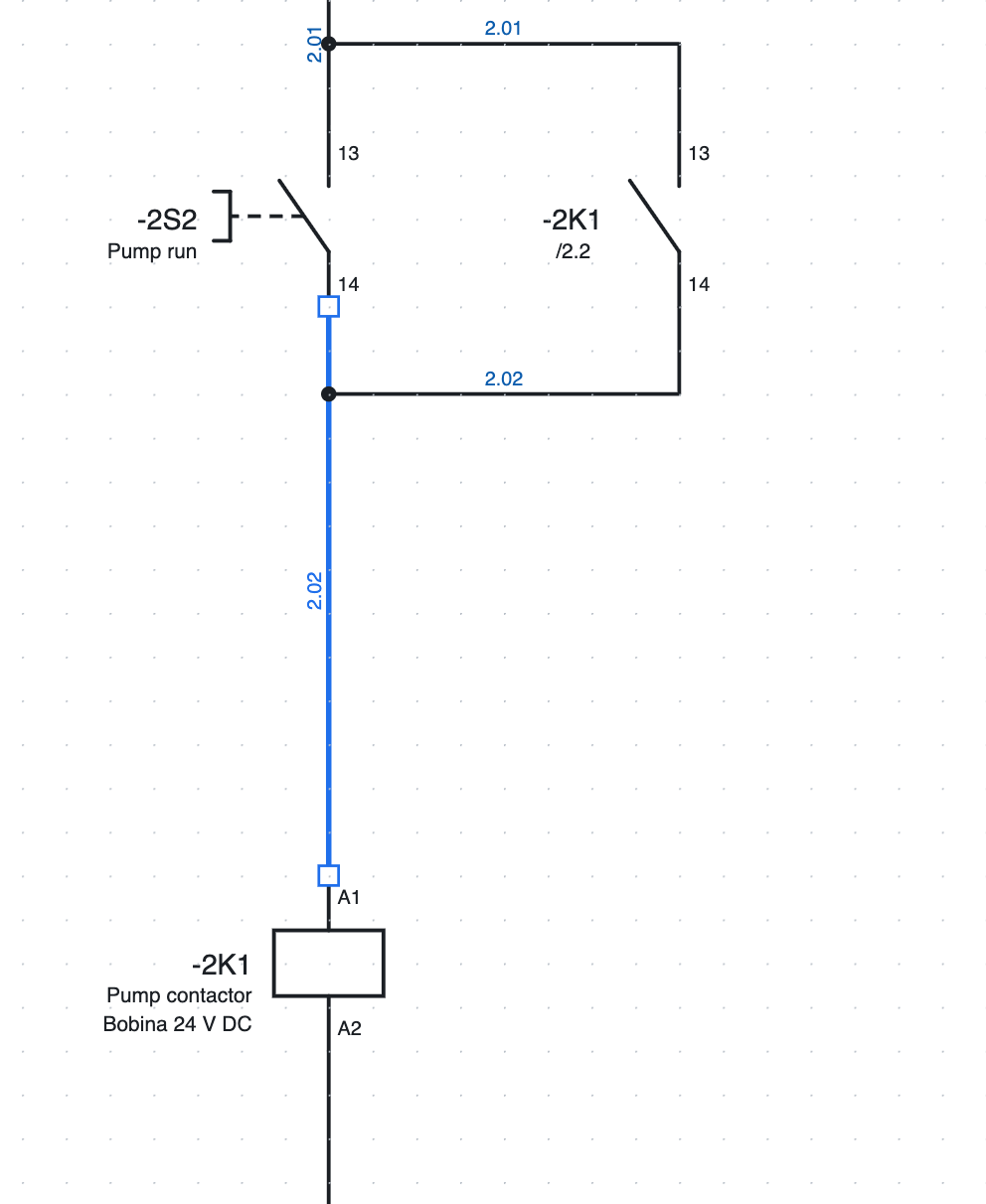
A selected wire shows its vertices as small squares.
- Drag a segment to move it in parallel: its ends stay connected.
- Drag a vertex or an end to lengthen, shorten or reconnect the wire.
- The cursor changes shape to show what you are dragging.
- To delete a wire select it and press Del.
#Moving symbols with their wires
When you drag a symbol, the connected wires follow it while you move it and stay orthogonal, bending into a Z if needed. A wire between two symbols moved together moves as a whole.
#Inserting a contact on a wire
If you insert (or move) a contact, a pushbutton or another component on top of a wire, the wire is split at its two connection points: there is no need to cut it by hand. The two pieces keep their colour and cross-section.
#Potential points
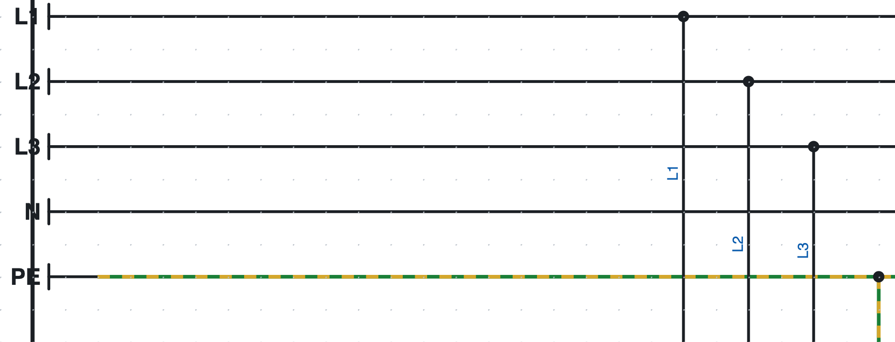
The L1, L2, L3, N and PE rails on page 1.
The potential point gives a name to a conductor: L1, L2, L3, N, PE, +24V, 0V…
- All conductors with the same name are connected, even on different pages.
- The name is written in the properties (Name); a new point is called
L1, the PE earth is calledPE. - The conductors of a potential can show the name instead of the wire number (Project properties ▸ Wire numbers ▸ Potentials).
- The check reports two different potentials on the same conductor (for example
L1connected toN).
#Interruption points between pages
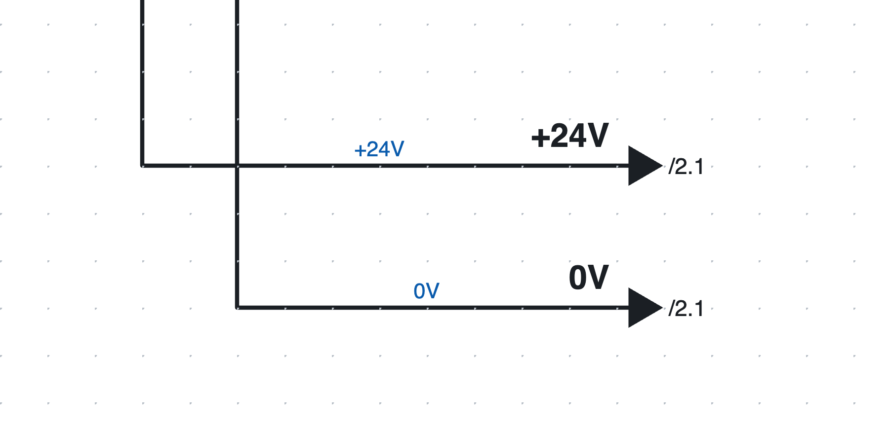
The +24V and 0V interruption points on page 1: the name above the wire, the destination pages next to
the arrow.
When a conductor continues on another page, a pair of interruption points is used. Each outgoing point is connected to one incoming point only, even when the name repeats (for example it is the wire number):
- At the end of the wire insert an Interruption point (outgoing). Its name is the wire number, if there
is one, otherwise
R1,R2…, and you can change it in Properties. - On the other page, at the start of the wire, insert an Interruption point (incoming): the list of the outgoing points still free appears, those with the same name first. Choose one: the incoming point takes its name and the two stay connected. The first entry (no outgoing point) leaves it free, when the outgoing point is not drawn yet. The same works the other way round: inserting an outgoing point you choose among the free incoming ones. The list is filtered as you type: each entry shows name, position and page of the point.
- In the Name field of the Properties the suggestions are the free interruption points and the other interruption point names; choosing a free one connects the two. The connection is changed in Properties ▸ Connected to. Renaming a point also renames its counterpart.
- Next to each arrow the page where the conductor continues appears (
/2.1). A click takes you to the page. On vertical wires name and page are written vertically, from bottom to top.
#Waiting, unpaired and star interruption points
When you insert an interruption point, the program takes its name from the wire number and looks for free interruption points:
- if there is exactly one free point with the same name, the two are connected straight away (a message in the report view says so);
- if there are several, the list opens with the first one already chosen: Enter confirms it;
- if there is none, the point stays waiting:
/…appears in orange next to the arrow until you draw its counterpart.
In Properties ▸ Connected to you choose the counterpart, put the point back to — waiting for the
counterpart (/…), or choose — no counterpart (the conductor ends here) when the conductor really ends
there: // then appears next to the arrow and the check reports it only as information, not as an error.
In the status bar, Waiting interruption points: N counts the points still to be paired; each click takes you to the next one. The check lists them as warnings.
Star source. A source with Properties ▸ Star connects to all free targets with the same name (for
example a +24V that goes to many pages) and shows the list of their pages. The check proposes the star
(with the 🔧 button) when a source is already paired and other targets carry its name.
#Conductor buses
When many wires run side by side (for example the three phases and the neutral feeding several loads) they can be grouped in a conductor bus, without drawing every line all the way.
- Choose the Wire bus tool in the toolbar (or Insert ▸ Conductor bus) and draw the line of the bus: it is
a thick line. In the Properties give the bus a name (optional, for example
400V ACor24V DC). - Draw the wires that reach the bus and the branches that leave it, so that they touch the line.
- On every wire touching the bus the conductor name (
L1,L2,PE…) appears, written next to the wire. It is chosen from a list that is filtered as you type.
The rules are simple:
- wires with the same conductor on the same bus are the same wire and have the same wire number;
- buses that touch, or buses with the same name on several pages, are a single bus: the conductors continue;
- the check (chapter 15) reports the wires that touch the bus without the conductor name and the conductors that enter the bus without leaving anywhere.
In the text format (chapter 17) the line of the bus is a wire with busfili=name
(busfili=_ if unnamed) and the conductor at the two ends of a wire is written with cond1= and cond2=.
#Texts
Text (or Insert ▸ Text) and a click on the page insert a free text. In Properties you change the text and its height in mm. Texts go into the translation dictionary (chapter 16).
#Images
Photos, logos or drawings are inserted in the schematic as images.
- Insert ▸ Image… and choose a PNG, JPG, SVG, GIF, WebP or BMP file; or paste an image from the clipboard with ⌘V (Ctrl+V).
- The image is moved by dragging it and resized by dragging the bottom-right corner: the proportions stay fixed, with Shift held down they are free.
- In the Properties you change position and size, restore the original proportions, turn on the border, choose whether the image sits below or above the schematic and replace it with Replace image….
- Images go into the PDF. In the DXF only a frame with the image name remains.
- Very large images are shrunk (to 1600 points on the long side) to keep the file light.
#Selecting, copying, moving
| Action | How |
|---|---|
| Select | click the element |
| Add to or remove from the selection | Shift + click |
| Box selection | drag on an empty area: left to right takes the contained elements, right to left also the ones touched |
| Select all | ⌘A |
| Move | drag, or arrow keys (4 mm; with Shift 16 mm) |
| Rotate, mirror | R, Edit ▸ Mirror |
| Duplicate | ⌘D |
| Copy, cut, paste | ⌘C, ⌘X, ⌘V; Paste here from the right-click menu pastes at the clicked point |
| Delete | Del or Backspace |
Copies get new tags and wire numbers; a coil and its contacts copied together stay connected. You can also paste into another project: the symbols and parts used are copied with the elements.
A circuit used often can be saved as a macro (chapter 13).
#Symbol texts always readable
When a symbol is rotated or mirrored, its internal texts (for example «M 3~» on the motor) are never upside down or mirrored: they always read from below or from the right, as the standard requires. This applies on screen, in the PDF and in the DXF.
Edit this page on GitHub · OpenWiring 2.0.6 · GPL-3.0