 OpenWiring
#7. Devices and parts
A device is a real component with a tag: the contactor -2K1 is a device, even if in the schematic it
appears as a coil, three power contacts and two auxiliary contacts on different pages. A part is a
product from a manufacturer's catalogue (code, description, dimensions, terminals) to be assigned to devices.
#Device data
| Field | Example | Where it appears |
|---|---|---|
| Description | Contattore pompa |
schematic (under the tag), lists, labels |
| Technical data | Bobina 24 V DC, 2,2 kW 400 V |
schematic, lists |
| Manufacturer | Schneider Electric |
bill of materials, purchase list |
| Type | LC1D09BD |
bill of materials |
| Order number | LC1D09BD |
bill of materials, purchase list |
| Notes | free text | device list |
| Function (=) | A1 |
full tag =A1+Q1-2K1 |
| Location (+) | Q1 |
full tag, grouping, layout |
| Part | DEMO.CT-09-24DC |
fills the empty fields with the catalogue data |
The data belong to the device: they are written on any element (coil or contact) and apply to all of them. Values typed by hand take precedence over those of the part.
Additional parts: a device can have several parts (for example a contactor and its auxiliary contact block).
In the navigator the Additional parts column is written as text, with the code and the quantity after ×:
LADN22 ×2; LA4DA2U. It can also be edited in bulk and in Excel.
Descriptions on the schematic: with Project properties ▸ Drawing ▸ Descriptions on the schematic turned on, description and technical data appear under the tag of the main element. The device field Texts on the schematic forces or hides them for that device only.
#Device navigator
The Devices tab (top right) shows all the devices of the project in a table that is edited like a spreadsheet.
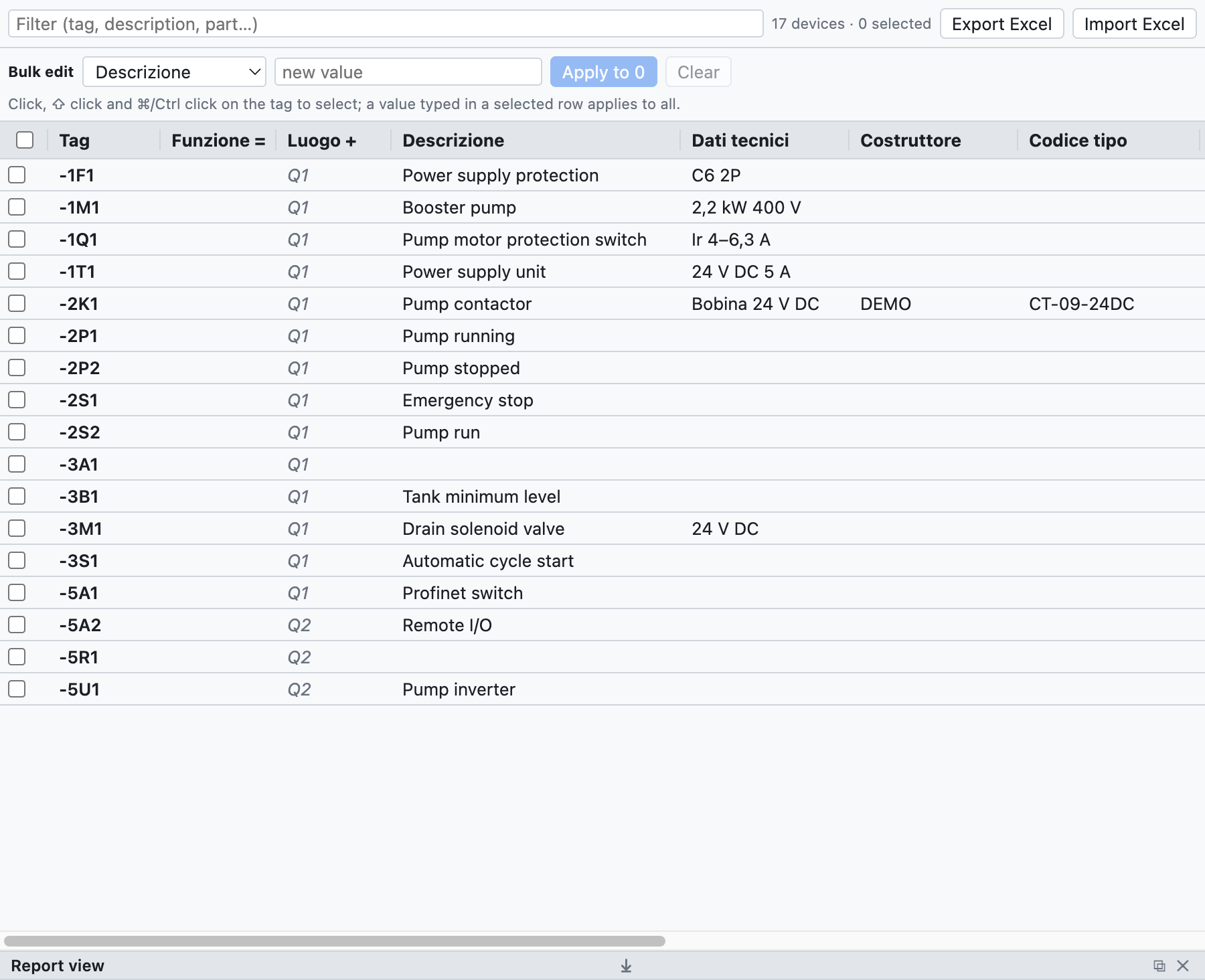
The navigator with the 17 devices of the example project. Values in grey italics come from the part or from the location of the page.
- Change a value: click in the cell, type and press Enter.
- Rename: change the tag in the first column; the contacts and the other representations change too. If the tag is already in use, the program says so and changes nothing.
- Filter: the field at the top searches in tag, description, part and the other fields.
- Select several rows: click on the tag, ⇧ click for a range, ⌘/Ctrl click to add, or the check boxes on the left.
- Go to the device: click on the position
/2.2in the last column.
#Bulk edit
To give the same value to many devices:
- Select the rows (for example all the devices of cabinet
+Q2, filtering forQ2). - In the Bulk edit row choose the field (Function =, Manufacturer…) and type the value.
- Press Apply to N. Clear deletes that field on all the selected devices.
Alternatively type the value directly in a cell of a selected row: it applies to all the selected rows. The whole change is undone with a single ⌘Z.
#Excel
- Export Excel saves the device table (tag, fields, position).
- Fill it in with Excel, even by another person, and use Import Excel: devices are recognised by the Tag column and only the changed fields are updated. Tags that do not exist in the project are reported in the report view.
#Copying properties
Right-clicking a device offers Copy properties: it copies all the data of the device (description, technical data, manufacturer, type, codes, part, additional parts, notes, function, location, user-defined properties) except the tag. On another device, or on a selection of several devices, the right-click menu offers Paste properties of -X: the copied data replace those of the device.
It is also how you replace a symbol with another: copy the properties of the old one, insert the new symbol, paste the properties and delete the old one.
#Structure =Plant +Location
In the tree, the Structure =Plant +Location node groups the devices first by function (=A1,
=A2…) and then by location (+Q1, +P1…), as IEC 81346 prescribes. Devices without a function or
without a location are at the bottom, in without function (=) and without location (+). A click on a
device opens it in the schematic.
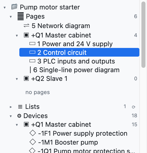
In the example project the devices have no function: they are all in «without function», divided between
cabinets +Q1 and +Q2.
The location of a device is the one written in its properties; if missing, the one of the frame it is drawn in on the network diagram, or the one of its page.
#Parts
The Parts tab is the personal parts library, saved on the computer and available in all projects.
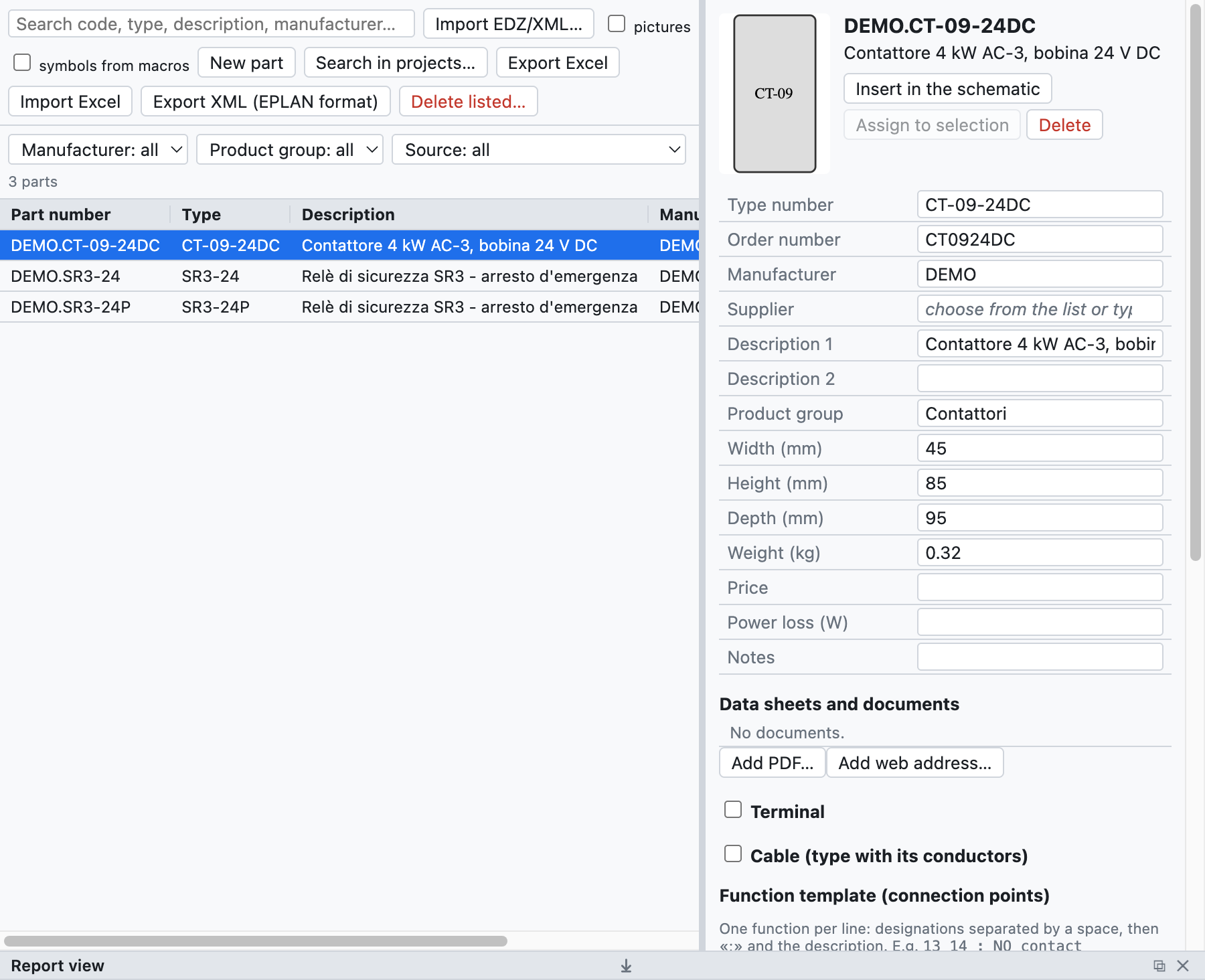
A contactor imported from an EDZ: data, picture, function template and symbol.
#Importing manufacturer data (EDZ)
- Download the EDZ file from the Eplan Data Portal or from the manufacturer's website (Schneider, Siemens, Phoenix Contact…). The EDZ is an archive in the Eplan Data Portal format with the part data.
- File ▸ Import ▸ Parts EDZ / XML / CSV… (or the EDZ button) and choose one or more files.
- The parts enter the library with code, type, order number, manufacturer, descriptions (in Italian if present, otherwise English or German), dimensions, weight, picture and function template (the terminals).
If the EDZ contains the manufacturer's drawing in a readable macro in EPLAN format, that drawing becomes the symbol of the part (category Macro EPLAN / costruttore in the library). Otherwise the part is drawn as an automatic black box: inputs at the top, outputs at the bottom, contacts and poles drawn inside.
XML files in the EPLAN format can be imported too; Export XML (EPLAN format) writes the parts to a file of the same format.
The commercial data CSV files (commercial_data.csv from the Eplan Data Portal) are imported with the same
command, also several files together: for each part they carry manufacturer, type, order code, group,
descriptions and long description. Parts already imported from EDZ are completed without losing symbol and
terminals. The links to data sheets and instructions appear in the part sheet, in the Documents section.
#The part sheet
Selecting a part you can see and change:
- the main data (code, type, order number, manufacturer, supplier, descriptions, group, dimensions, weight, price, notes);
- the function template: one line per function, with the terminals separated by spaces and the
description after
;(for example13 14 ; Contatto NA); - the symbol in the schematic: one of the basic symbols, an imported component or the manufacturer's drawing.
#Using parts
- Insert in the schematic: inserts the symbol of the part, already assigned.
- Assign to selection: select a device in the schematic and assign the part to it. Alternatively choose the part in the Part field of the device properties.
- The parts used are copied into the project (Project parts in the tree), so the
.ecadfile stays complete on another computer too.
#The parts database
The personal library is a database that travels from one plant to the next: data written once is not retyped.
- In the Part field (in the Properties, in the Devices navigator and in the Connectors tab) you write or choose a code. If the code is new, it becomes a part of the library, with the manufacturer, type, order code and technical data of the device. The next time the code is used, the data fill in by themselves.
- If the part already exists and the data of the device differ, Save these data in the part writes them into the existing part.
- Description and manufacturer of additional parts also go into the library.
#New part
New part creates an empty part to be filled in by hand: useful for components without an EDZ.
Edit this page on GitHub · OpenWiring 2.0.6 · GPL-3.0