 OpenWiring
#11. Networks, locations and single-line diagram
#Locations
A location is a physical container: electrical cabinet, pushbutton station, machine side, junction box,
field. Its code is the + part of the tag (+Q1-2K1).
- Project ▸ New location…, or + Location in the project properties.
- Type the code (
Q1,BM,P1), the name (Quadro master) and the type. - Assign the pages to the location with Page properties ▸ Location (section): a new page stays in the location of the page it starts from.
Every device is in a location: the one written in its properties, otherwise the frame it is drawn in on the network diagram, otherwise the location of its page.
Where the locations are seen:
- the tree groups pages and devices by location;
- the device list shows the full tag (
+BM-1M1); - the device labels are grouped by location;
- a layout page assigned to a location proposes only its own devices.
#A component of one cabinet wired to another cabinet
Typical case: a sensor mounted in +Q2 goes to a PLC input of +Q1. If you draw it on the
input page of +Q1 with the +Q2 location box, the tag is right (+Q2-B1) and the sensor goes into the
+Q2 lists. The schematic, though, is on the +Q1 pages: whoever wires +Q2 and receives only its pages
does not see it.
The recommended technique is to split the circuit at the cabinet boundary, on the terminals:
- on the +Q1 page: PLC input → terminal
-X1:5→ cable-W12→ interruption point to the +Q2 page; - on a +Q2 page: interruption point from +Q1 → cable
-W12→ terminal-X2:5→ sensor-B1.
Each component is drawn on the pages of the cabinet where it is mounted; the link between the cabinets is the cable, which appears in the cable drawings of both; the references are clickable in the PDF. Each cabinet has its own terminal entry and each wirer works up to the terminal.
The checks warn when a device of a cabinet, push-button station or junction box is drawn on the pages of another cabinet: +Q2-B1 is drawn on page 310 of cabinet +Q1: printing only +Q2 it does not appear. Machine and field locations do not count, since they are usually drawn on the cabinet pages; nor does a sub-location of the same cabinet (e.g. the door).
If you prefer to keep the component next to the PLC input, when printing only some cabinets tick Add the pages of other cabinets with devices of the chosen cabinets in the PDF (chapter 18).
#Network diagram
The network diagram shows on a single page all the nodes of the plant and the bus connections between the cabinets.
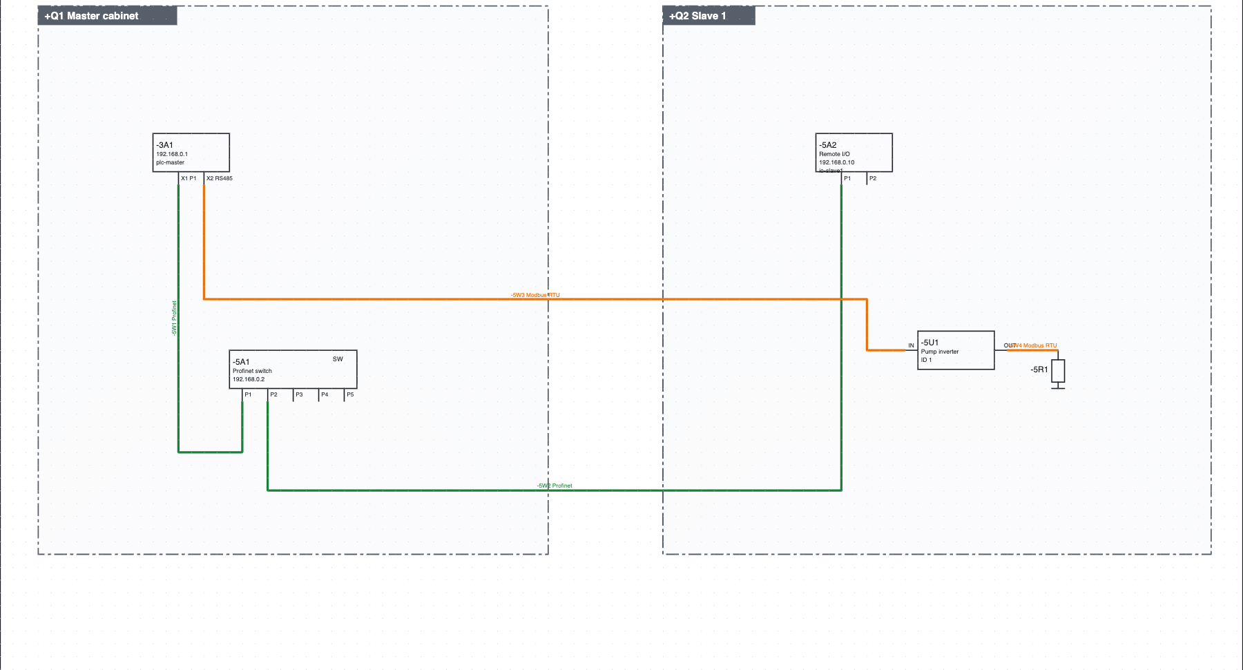
The network diagram of the example project: CPU -3A1 and switch -5A1 in cabinet +Q1, remote I/O
-5A2 and inverter -5U1 in cabinet +Q2, connected with Profinet (green) and Modbus RTU (orange).
- + Network under the tree creates the page.
- Cabinet in the toolbar: click on two corners to draw the frame of a cabinet and choose its location. The nodes inside the frame belong to that cabinet.
- From the Networks and buses category insert the nodes: two-port node (IN/OUT or P1/P2), one-port node, 5-port switch, termination. A node takes the tag of an existing device (the CPU, an inverter…) and becomes one of its representations.
- Choose the protocol next to the Bus button and connect the ports like a wire.
#Protocols
Profinet, EtherCAT, Modbus TCP, Modbus RTU, Profibus DP, EtherNet/IP, CANopen, IO-Link, RS485, Ethernet. Each protocol has its own colour and its name written on the line. Buses get no wire number and are not among the electrical connections. An existing wire is turned into a bus from its properties (Network / bus).
#Network cables
Every bus connection is a cable: it takes a tag by itself (-5W1, written on the line next to the
protocol). In the connection properties you give type (proposed per protocol, for example
Profinet tipo A 2×2×AWG22), length and part. Network cables appear in the cable list with the ports at the
ends (-3A1:X1 P1 → -5A1:P1), in the labels and, with the part, in the bill of materials in metres.
A cable that continues on another page through a pair of cross-references (for example from the robot
controller to the robot page) is one cable: it has one tag on all segments. A segment with the tag given by the program takes the cable's tag on its
own, even if you pair the cross-references after drawing it. Changing the tag, type,
length or part on one segment changes the others too. If the segments have different tags the check
reports it, and the Use -… on all segments button puts the tag of the segment on the first page on
all of them. Give the cross-references the same name as the cable (1102W1): next to the
cross-reference the tag is not repeated. To show or hide it on a segment use the eye of Cable tag;
the eye of Wire number turns off all the text on the connection.
#Lists and checks
- Network connections: protocol, ports, cabinets, connections between different cabinets.
- Network nodes: address, protocols, cabinet.
- The check reports repeated addresses on the same network (also through switches) and Ethernet ports with more than one connection (a switch is needed). Multi-drop buses (Modbus RTU, Profibus, CANopen, RS485) allow several nodes on the same segment.
#IP address plan
- Project ▸ New IP network: name, address and prefix (
192.168.0.0/24), gateway, protocol that uses it and first address to assign. - In the properties of each node there is the IP address field, separate from the bus address (Profinet name, Modbus ID…). The IP is written in the frame of the node.
- Project ▸ Assign IP addresses gives the first free address to the nodes connected with Profinet, Modbus TCP, EtherNet/IP or Ethernet that have none (not EtherCAT and the serial buses).
- Project ▸ IP address plan opens the list: IP, mask, gateway, network, device, name, protocols, location, including the PLC stations.
The check reports repeated IPs, invalid ones, ones outside the networks or equal to the network or broadcast address, and gateways outside the network.
#Network addresses
Project ▸ Network addresses… (also from the Networks group of the Project ribbon tab) opens a table with all devices that have a network port, including those without an address yet, and the PLC stations.
How ports are found. A port is any pin touched by a bus wire (Profinet, Ethernet, Modbus, EtherCAT…) and any network node. Symbols need no special pins.
- The IP ports of a device (Profinet, Ethernet, Modbus TCP, EtherNet/IP) form a single interface, like an integrated switch: one IP and one name.
- Each non-IP bus (Modbus RTU, CAN, EtherCAT…) has its own interface with its own address.
- Separate… gives some ports an interface of their own, with a different IP and name (for example X2 outside the switch of X1). Merge puts them back into the main interface.
You type directly in the IP address and Profinet name / address columns; Enter confirms. For a PLC station the values stay in sync with the stations table. At the bottom:
- Assign IP: a free IP of the right network to IP interfaces that have none (an IP network is needed first);
- Automatic Profinet names: a name from tag and location (
+Q1 -2A1→q1-2a1, withpn-in front if the name would start with a digit) for Profinet devices without a name; names already written stay; - List and export: the same table among the reports, to print or export to PDF, CSV and Excel.
The last column shows the problems: duplicate IPs or IPs outside the network, invalid or duplicate Profinet names.
#Single-line diagram
The single-line diagram represents the power distribution with a single line for each outgoing feeder.
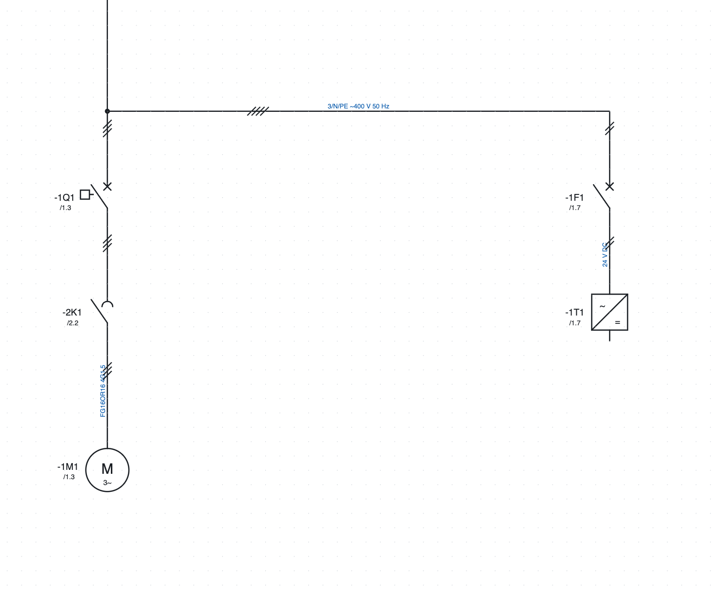
The single-line diagram of the example project: the same tags as the multi-line one, with the reference to their position.
- + Single-line under the tree creates the page.
- From the Single-line category insert circuit breaker, motor protection switch, disconnector, fuse, contactor, motor, transformer, inverter, power supply, load.
- Give each symbol the same tag as the device in the multi-line diagram: the clickable reference to its
position appears (
/1.3). - The lines have the number of conductors (Conductors (ticks)) and a text (
3/N/PE ~400 V 50 Hz).
The lines of the single-line diagram do not count as conductors, wire numbers or list entries: the real electrical schematic remains the multi-line one.
Edit this page on GitHub · OpenWiring 2.0.6 · GPL-3.0