 OpenWiring
#3. Your first project
In this exercise you draw the control circuit of a pump: a stop pushbutton, a start pushbutton, the contactor with self-holding and a running lamp, supplied at 24 V. It takes about twenty minutes and at the end you know the basic commands: inserting symbols, drawing wires, filling in data, checking and exporting.
#Step 1 – New project and supply rails
- File ▸ New project. An empty page opens, page 1.
- Click the page name in the tree and, in Properties, type the Description:
Pump control. The title appears in the title block. - In the library, category Terminals and connections, choose Potential point and click at the top
left of the page. The point is named
L1: in Properties ▸ Name type+24V. - Insert a second potential point at the bottom and name it
0V. Press Esc to finish inserting. - Press W (Wire tool), click the
+24Vpoint and then the right-hand end of the page; finish the wire with a double click. Do the same for the0Vrail.
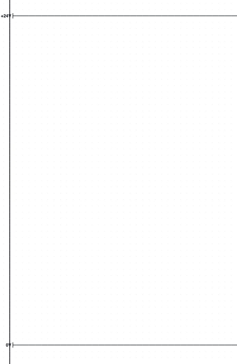
Step 1: the supply rails.
Why potential points? All conductors with the same name (
+24V,0V,L1,PE…) are connected to each other, even on different pages. The lists and the check know this.
#Step 2 – The symbols
- Category Commands: choose NC pushbutton and click below the
+24Vrail, in column 1–2. The pushbutton automatically gets the tag-1S1(page 1, letter S, first on the page). - Still in Commands, NO pushbutton, lower on the same vertical: it becomes
-1S2. - Category Coils and contacts: Relay/contactor coil, lower still: it becomes
-1K1. - Press Esc.
If a symbol must be turned, press R (rotate by 90°) before inserting it; after inserting, rotate it with R on the selection. Symbols snap to the 4 mm grid.
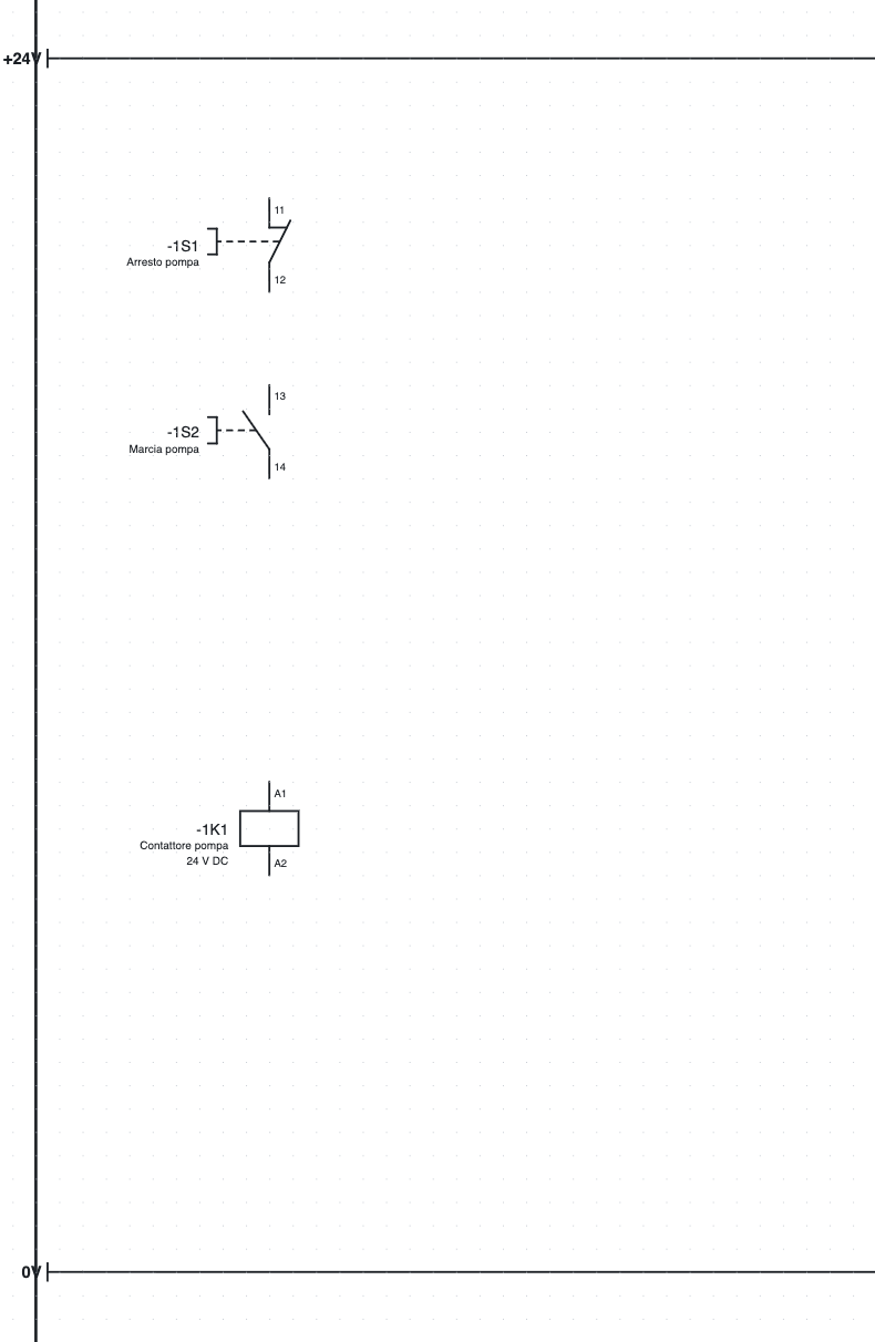
Step 2: pushbuttons and coil, still without wires.
#Step 3 – The wires
- Press W. Click the
+24Vrail above pushbutton-1S1: the wire starts from the point on the rail. - Click the upper connection point of the pushbutton (
11): the wire ends by itself when it reaches a connection point. The available points are highlighted by small green circles. - In the same way connect
-1S1:12to-1S2:13,-1S2:14to-1K1:A1, and-1K1:A2to the0Vrail.
Where a wire reaches another wire, the program creates a junction and draws it with a dot. Two wires that cross without a dot are not connected.
Automatic connection. When you insert or move a symbol, its free connection points connect by themselves to the points facing them on the same line: two symbols placed one below the other on the same vertical are already joined by a wire. It is handy for circuits drawn in columns; if you prefer to draw every wire by hand, switch it off in Project properties ▸ Drawing ▸ Automatic connection.
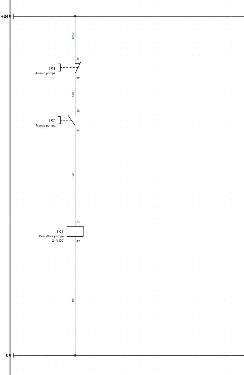
Step 3: the connected control circuit. The blue wire numbers were assigned automatically.
#Step 4 – Self-holding and lamp
- Category Coils and contacts: NO contact. Insert it to the right of the start pushbutton.
The NO contact: which device? window opens with the project's coils: choose
-1K1and press Enter. The contact gets terminals13-14. If you confirm without choosing, it stays a new device (-1K2). - Connect it in parallel with the start pushbutton: one wire from the segment above
-1S2to the contact, one wire from the contact to the segment below-1S2. The T-junctions form by themselves. - Insert a second NO contact further right: the window already suggests
-1K1, the last coil chosen; press Enter and the contact gets terminals23-24. - Category Loads: Indicator lamp below the contact: it becomes
-1P1. - Connect
+24Vrail → contact → lamp →0Vrail.
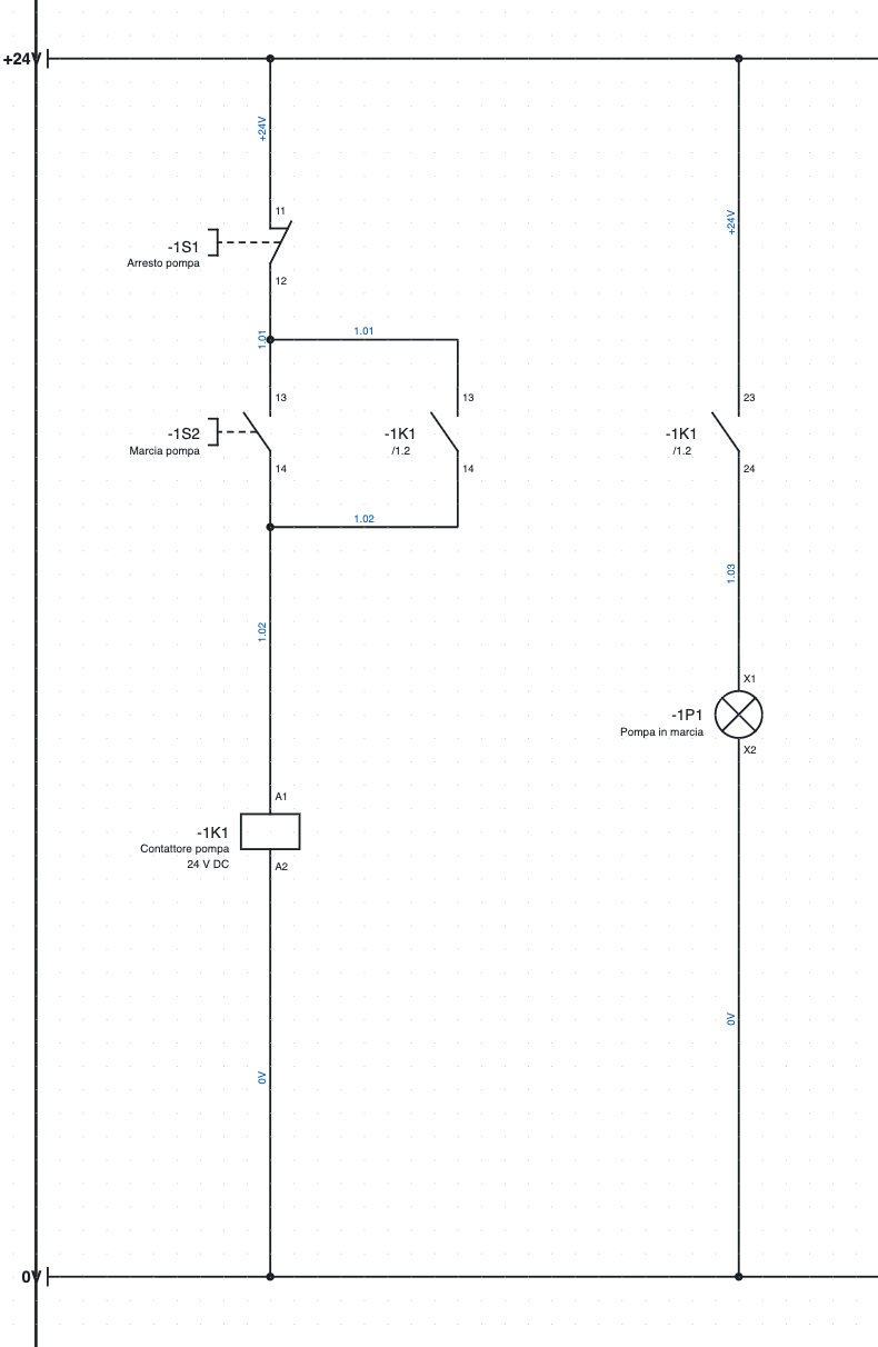
Step 4: self-holding -1K1 13-14 and the running lamp controlled by -1K1 23-24.
Below each contact appears /1.2: the position of the coil (page 1, column 2). At the bottom of the
page, below the 0V rail, the contact image of the coil appears with the positions of the contacts
(/1.2 13-14, /1.4 23-24). Clicking a cross-reference takes you to the connected element.
#Step 5 – The component data
Select coil -1K1. In the Properties panel fill in:
- Description:
Pump contactor; - Technical data:
24 V DC; - if you know it, the part, or else manufacturer, type and order number.
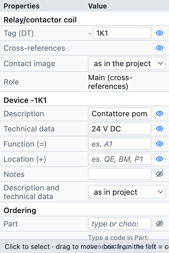
The properties of coil -1K1: tag, device data, ordering, connection points and position.
Description and technical data appear on the schematic below the tag and go into the lists. They belong to
the device: written on the coil, they also apply to its contacts. Fill in the pushbuttons too
(Pump stop, Pump start) and the lamp (Pump running).
#Step 6 – Check
Press Check in the toolbar. The Checks tab opens with errors (●), warnings (▲) and unused data (○). Clicking a row takes you to the element.
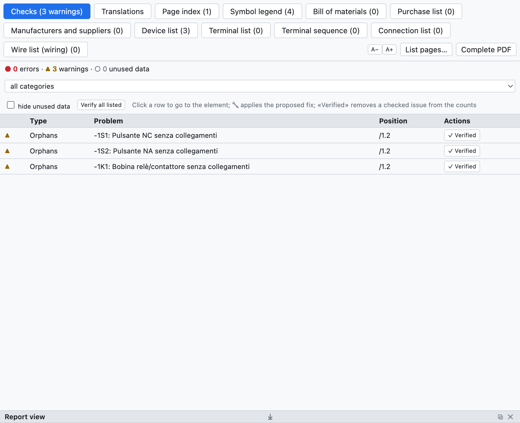
This is what the check reports if you run it after step 2, when the symbols are not yet connected.
With the finished schematic the check finds no problems. Try deleting a wire: warnings about free connection points appear.
#Step 7 – Saving and exporting
- Save (⌘S) and choose the file name, for example
Pump control.ecad. - PDF in the toolbar: keep Those ticked in the list below (all are ticked at first) and press Export. The PDF has the index, the lists at the end and clickable cross-references.
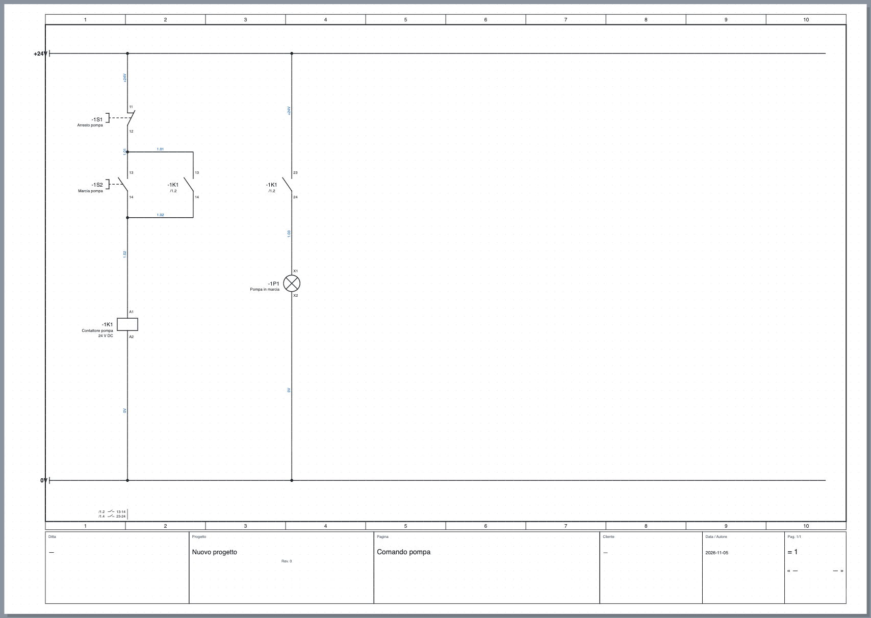
The finished page, with the title block filled in from the project data.
#What next?
- The title block data (company, customer, drawing number) are filled in the project properties: chapter 4.
- To connect different pages use interruption points: chapter 5.
- For the power circuit (motor protection switch, contactor, motor) open page 1 of the example project.
- The same schematic can be drawn by the AI assistant from a description in words: chapter 17.
Edit this page on GitHub · OpenWiring 2.0.6 · GPL-3.0